Convert to a 3-Wire Configuration Using a Dual Run Capacitor
Here’s a concise, safety-first, step-by-step procedure to convert and wire a 4-wire condenser fan motor so it’ll work in place of your original 3-wire unit:
Power Off & Lock Out
Shut off the condenser unit at the breaker (or pull the contactor’s fuse).
Verify there’s no voltage at the fan motor leads with a multimeter.
Tag and lock out the disconnect to prevent accidental energization.
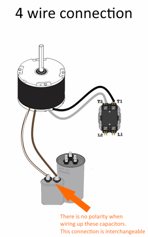
Identify & Label Motor Leads
Black – L1 (hot)
White – L2 (neutral/common)
Brown (solid) – Run-capacitor lead
Brown-with-white stripe – Capacitor common (internally tied to white)
Isolate the Extra Capacitor Wire
Cut the brown/white-stripe lead back to the housing.
Place a properly sized, insulated wire nut on that cut end to cap it.
Secure the capped lead so it can’t touch anything live.
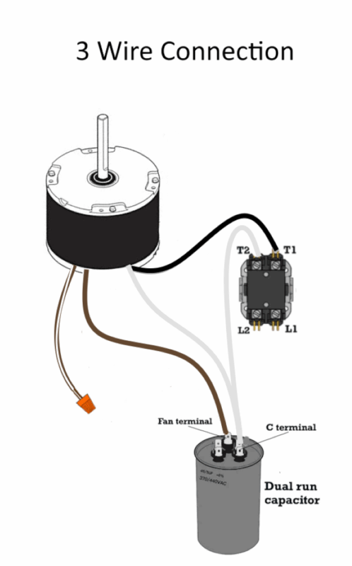
Wire the Remaining Leads to the Contactor & Capacitor
Black → Contactor T1
Connect the motor’s black lead to the T1 terminal on the contactor.
White → Contactor T2 (via capacitor common)
Connect the motor’s white lead to the C terminal of the dual-run capacitor.
Then run a short jumper from the C terminal to the contactor’s T2.
Brown (solid) → Capacitor FAN terminal
Connect the motor’s solid brown lead to the FAN (run) terminal on the same capacitor.
Reconnect & Ground
If there’s a green or green-yellow lead on the motor, attach it to the chassis ground/contactor ground screw.
Double-check all connections are tight and wire nuts are fully seated.
Secure & Neaten
Use cable ties or clamps to bundle the motor leads neatly.
Ensure the capped brown/white lead is tucked away safely.
Test Operation
Remove lockout/tagout and restore power.
Energize the condenser contactor and observe the fan for proper rotation and smooth start.
If the fan spins the wrong way, swap the two speed-selection leads (often orange/yellow) per the motor’s label.
Why This Works
Internally, the brown/white wire is commoned to the white lead, so removing it simply bypasses the extra capacitor circuit without affecting motor performance.
You’re left with the exact same three-wire arrangement your original motor used—black for power, white for common, and brown for the single run capacitor.